Introduction
Mass timber buildings incorporate a diverse array of fastening systems, including screws, nails, bolts, and staples. Screws are gaining favor due to their significant engineering and architectural benefits.
With the availability of fully threaded and longer screws, these fasteners are becoming increasingly popular in timber construction. The primary advantage of screws is their exceptional holding power, stemming from their threaded design. These threads enhance the contact surface area with the wood, improving overall grip. This engagement allows screws to more effectively resist both axial forces and lateral loads, making them a highly dependable option in timber construction.
Moreover, screws reduce the risk of timber splitting and can be installed at various angles to the grain. Where reassembling might take place, their removal causes minimal damage to the timber. Screws also demand less tooling and preparation for installation, adding to their practicality. Architecturally, when there is a need to conceal connections, screws offer an advantage as they can be embedded within the timber, maintaining aesthetic integrity.
Basic Screw Terminologies
A simple screw will have the following parts.
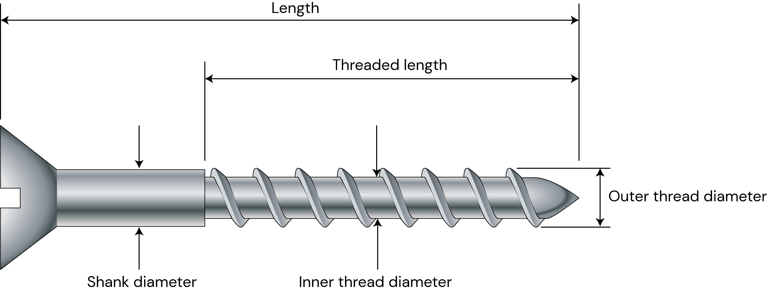
Figure 1 Typical screw
Head of a screw: these can be of many types depending on the purpose of screw to be applied for. Screws can have countersunk heads, cylinder heads, washer heads, hexagonal heads, etc. Washer heads have higher head diameters and are preferable for clamping of two members together while cylinder heads have a smaller head diameter and are preferable if the screws are to be drilled below the surface of a timber member.
Shank: shank is the smooth non-threaded part of a screw.
Thread: screw threads are sometimes formed by threading down the original shank rod or by hardening after rolling the thread on the shank.
Inner thread diameter is the diameter of the inner root.
Outer thread diameter is the diameter of the outer thread and is mostly labeled as the nominal diameter.
Screw tip: screws can have a varying tip used for self- drilling.
Types of Screws
Depending on the application of the screw to be used, screws may be of many types.
Based on the portion of the threaded part, screws can be fully threaded or partially threaded. Fully threaded screws are used to utilize their high withdrawal capacity because of longer thread lengths and can be used for reinforcing purposes. Partially threaded screws are mostly used for clamping two members together. These screws can be widely used in post and beam applications.
Reference: Designers guide to Eurocode 5 Design of timber buildings EN 1995-1-1 CL 8.7 and EN 14592
EN 1995:2004 classifies screws based on their formation as self-tapping screws and smooth shank screws. Self-tapping screws are formed by hardening after rolling down the thread. In these types of screws, the outer diameter is referred to as the nominal diameter. There are also a second class of screws that are formed by threading down the original shank rod, and these produce a screw with the smooth shank diameter being the nominal diameter. EN 1995:2004 calculations for axially loaded screws are the same for both types of screws.
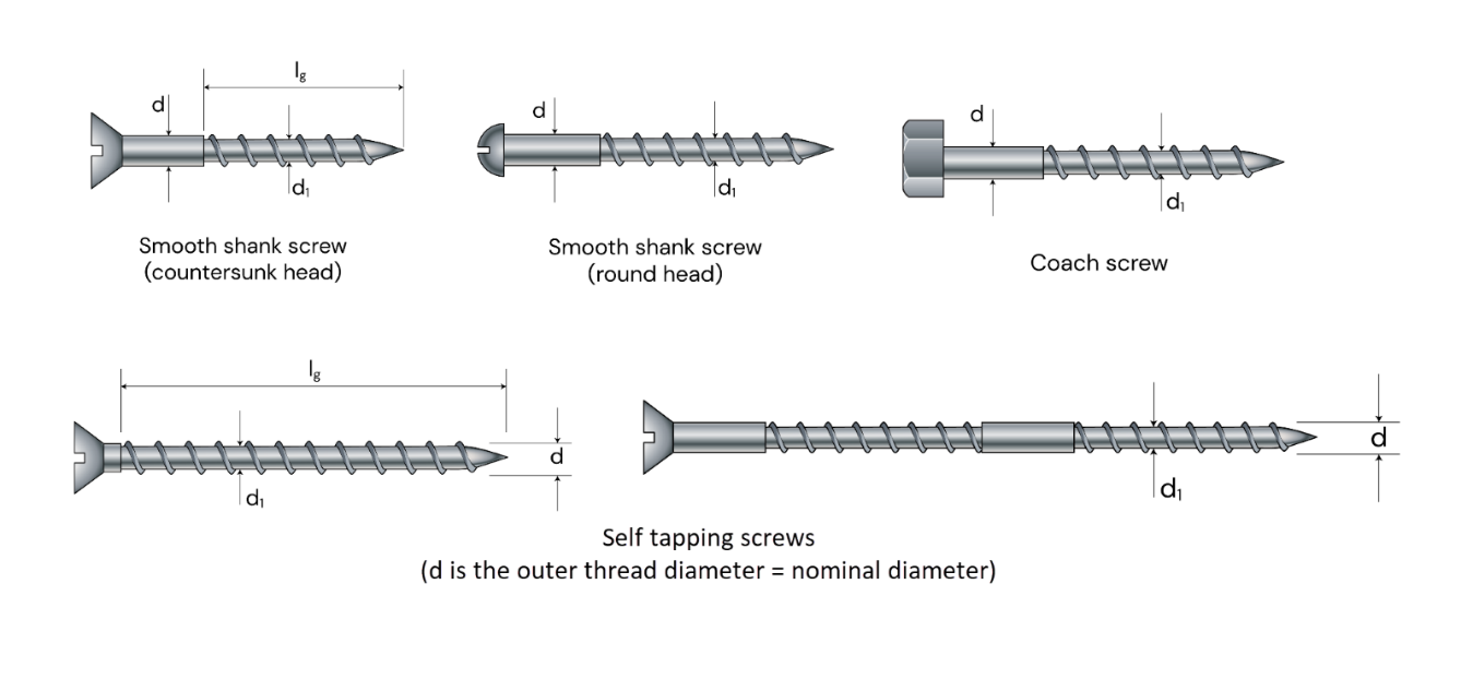 Figure 2 Smooth shank screws and self-tapping screws according to EN 1995:2004
AS 1720.1:2010 has screws and coach screws in two different sections of the code. Screws have usually a lesser diameter and bigger length range than coach screws.
Applications of Axially Loaded Screws
The design approaches of screw design can be different depending on the design code chosen, the type of load that they are resisting, and the type of connection system the screws are in. Axially loaded screws can be widely used for connecting two members or in reinforcing of a single member.
Connecting Two Members
When connecting two members screws can be loaded in withdrawal while transferring an axial load from one member to another. An example of a screw loaded in withdrawal while used as a connection of two members can be seen in a typical post and beam construction.
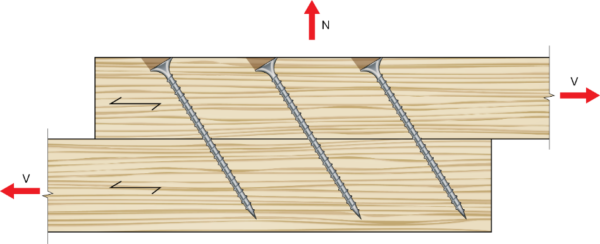
Figure 3 Axially loaded screws used to connect two members
Reinforcement of Members
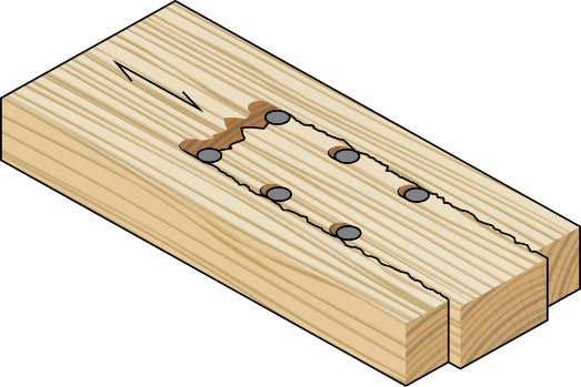
Axially loaded screws are mostly used in fixing two members together but can also sometimes be used in single member connections for reinforcing purposes. An example for this can be beam penetration reinforcements and notch reinforcements. When screws are used in these types of connections usually, they are being used to resist tension perpendicular to grain forces which would cause splitting of the timber member. The design approach for these types of connections can be like two member connections, taking the thickness of the member above crack line as member one and the rest of the thickness below crack line as member two, depending on the location of the screw head.
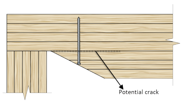 Figure 4 Axially loaded screw used as reinforcement
Introduction to the Approaches of Axially Loaded Screw Design
EN 1995:2004 considers the withdrawal resistance; the head pull through and the tensile capacity of a screw in determining the resistance of axially loaded screws. When subjected to an axial load, screws can be withdrawn from either of the members due to the applied force which is accounted in the withdrawal resistance of screws. There is also a possibility of the screw head to be pulled through head side timber member which is accounted by head pull through resistance. Another failure mechanism of screws under axial loads is tensile failure and occurs when the applied force is greater than the tensile capacity of the screw.
On EN 1995:2004 the withdrawal resistance calculations are based on formulas that account different factors. The withdrawal capacities usually consider the angle between grain direction and screw axis, the characteristic density of timber, the withdrawal parameter of screw, the screw diameter and the thread length inside the member considered which is also called effective length of screw. The head pull through considers the head diameter of the screw and a head pull through parameter of the screw. Screws with larger head diameters and screws with washer heads have a higher head pull through capacity. For some types of screws however, the head pull through capacity may not be governing and only tensile capacity and withdrawal capacity will be considered in determining the resistance of the screw connections. Also, in connections fixing steel members to timber, the steel will be the head side member and head pull through capacity will not be applicable here because the screw head wouldn’t punch through a steel plate.
Reference: EN 1995:2004 CL 8.7.2.
|
Characteristic Withdrawal Capacity |
 |
|
Characteristic Pull-through Capacity |
 |
|
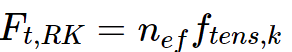
Characteristic Tensile Capacity |
 |
AS 1720.1:2010 has a different approach in considering the resistance of screws under axial loads. To design screws, AS 1720.1:2010 uses a tabulated characteristic withdrawal value per an effective length of screw is given in a tabulated manner. One can directly read the characteristic capacity of a single screw having the timber type which is represented by the joint group and the shank diameter of the screw. This capacity is then multiplied by an effective screw length and different modification factors to give the design capacity. The tensile capacity of the screws is also considered in the final design capacity. For coach screws, in addition to the above two, crushing under head of coach screws is also considered.
Characteristic capacities are calculated for a single screw in both codes and then multiplied by the effective number of screws in EN 1995:2004 and directly by the number of screws in the AS 1720.1:2010.
In addition to the above design approaches, there are some specific issues that need special attention.
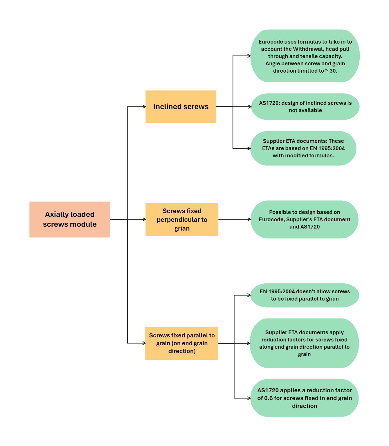
Axially Loaded Screws at an Angle
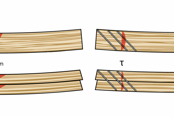
Inclined screws can also be used in different types of connections. The use of inclined screws can sometimes be preferred. They can be more appropriate in some types of connection details where the use of non-inclined screws is impractical because of the geometry of the connection. Inclined screws can also decrease the risk of splitting especially if the screws are to be inserted in the end grain direction.
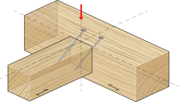
Figure 5 Beam to beam connection detail where inclined screws are preferred
In situations like this, usually the applied load is not parallel to the screw axis. The withdrawal resistances calculated are along the screw axis and there is a need to calculate the component of this resistance along a direction parallel to the applied load. The component of this resistance is then compared with the applied load to compute the axial capacity of the screws.
According to EN 1995:2004, the capacity of laterally loaded screws is computed using European Yield model Equations, also called Johanson’s equations. EN 1995:2004 limits the use of these equations for screws which are fixed perpendicular to the grain direction. For inclined screws subjected to lateral loading, the component of the axial resistance is taken to calculate the lateral load carrying capacity of screws.
On the AS 1720.1:2010 code, the use of inclined screws is not accounted.
.
Axially Loaded Screws in Steel to Timber Connections
Axially loaded screws can also be used to fix steel plates with timber members. On EN 1995:2004, the resistance of an axially loaded screw in steel to timber connections will be the governing value from the withdrawal and the tensile failure of the screw. The head pull through of the screw will not be governing here because pulling out of the screw head through the steel plate will not happen.
End Grain Vs Side Grain Approaches
Regarding the use of screws fixed in end grain, general recommendations advise against fixing screws in end grain because this might cause splitting of the timber member. The design approach of screws fixed in end grain vary between EN 1995:2004 and the Australian code. EN 1995:2004 limits the use of screws directly inserted in the end grain direction. The minimum allowed angle between screw axis and grain direction is 300 in EN 1995:2004. In the AS 1720.1:2010, one can use screws directly inserted in end grain, parallel to the grain direction by using a grain orientation factor k13 which is equal to 0.6. To design screws directly inserted parallel to the grain direction under EN 1995:2004 code, one can choose to design based on the screw supplier’s ETA.
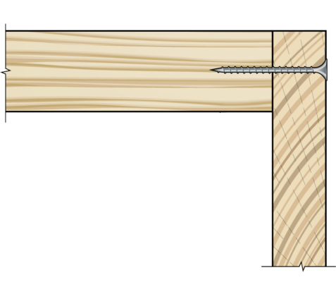
Figure 6 Screws in end grain
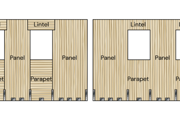
Spacing, Edge and End Distances for Screws
In addition to the capacity checks, screw geometry also needs to be fulfilled. Both EN 1995:2004 and AS 1720.1:2010 have requirements for the spacing of the screws both along grain direction and perpendicular to the grain direction, end distances and edge distances. These geometry requirements are given based on the nominal diameter of the screws on EN 1995:2004 and based on shank diameter of the screws on AS 1720.1:2010.
Since AS 1720.1: 2010 doesn’t consider inclined screws, the minimum geometry requirements can be measured from the screw head. In contrast axially loaded screws in EN 1995:2004 can be inclined and the end and edge distances must be measured from the center of gravity of the screw inside a member to the end and edge of the grain respectively.
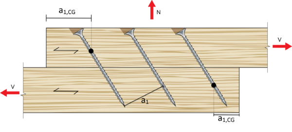
Figure 7 End distance of axially loaded screws according to EN 1995:2004
The Axially Loaded Screw Module in CLT Toolbox
The CLT toolbox’s axially loaded screws module is an advanced tool specifically tailored for optimizing screw connections in mass timber buildings. The inclusion of inclined screws, a significant aspect of timber design, enhances the versatility of the calculator. Users have the unique option to input the screw inclination angle, both along the grain direction and perpendicular to the grain direction, accommodating various design scenarios in mass timber structures.
CLT Toolbox’s axially loaded screws module has an option to design based on EN 1995:2004 or AS 1720.1: 2010 design codes. Under EN 1995:2004 the user can also choose to design based on a screw supplier’s ETA. EN 1995:2004 allows the use of inclined axially loaded screws whereas when AS 1720.1:2010 code is chosen only screws with no inclination could be designed. For aesthetic purposes screw heads sometimes need to be embedded inside timber members. This module, and our laterally loaded screw module also has an option for the user to use a desired embedment depth in which the screw head can be drilled inside a timber member.
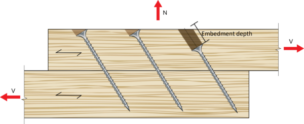
Figure 8 Screw embedment option
Regarding geometry checks, user can input the screw head’s locations in reference to member ends and edges. Our calculator will then automatically calculate the end and edge distances of the center of gravity of the screws and compares with minimum code requirements according to both AS 1720.1:2010 and EN 1995:2004. Some suppliers have their own geometry requirements for some specific screws. That is also included in our axially loaded module as well as throughout our screw calculators.
 Conclusion
Connections design is one of the main challenges of timber structures. Out of the many possible ways to connect members of mass timber buildings, usage of both partially threaded and fully threaded screws are gaining a wide range of acceptance due to their availability, ease of use, aesthetic value, and high strength. Solving screw connections design would therefore be a great help to the mass timber industry.
The CLT toolbox’s axially loaded screws design module is a comprehensive and user-friendly tool for professionals in timber design. It combines functionality with accuracy, adhering to international standards and accommodating a wide range of design scenarios in the evolving field of mass timber construction. Users of this module can use EN 1995:2004 for axially loaded screws and laterally loaded inclined screws and for the AS 1720.1:2010 code using non inclined screws.