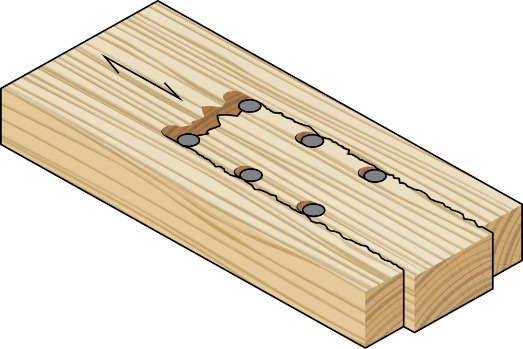
Beam Penetration in mass timber involves carefully planning and executing circular or rectangular openings in beams to integrate essential services. Those openings are used for transferring electrical conduits, plumbing pipes, and other. The pipes and other materials that pass through the penetration do not rest on it; they are supported independently. This is important to prevent increasing the tensile force demand around the penetration.
Penetration for a beam is single or multiple based on the service and capacity of the beam. Also, the penetration hole may be circular, rectangular, or both together with different size and location arrangement.
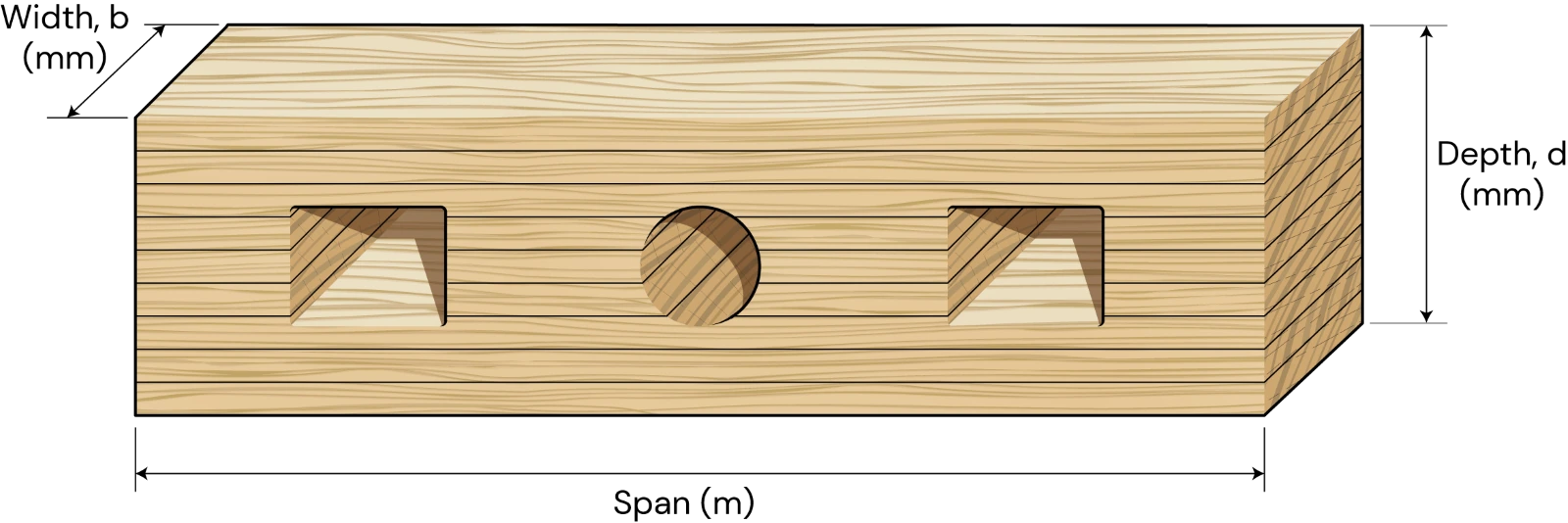
Figure 1: Beam Penetration
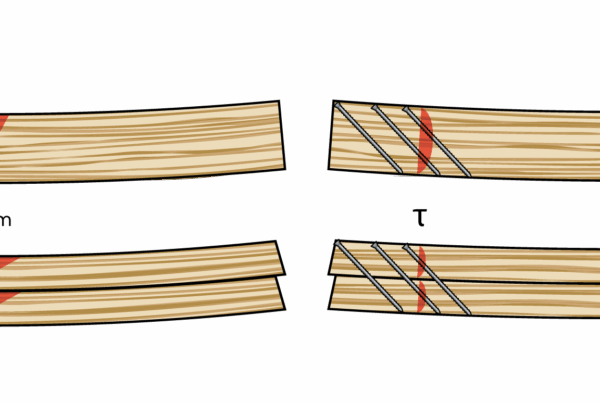
Reinforcement is added for penetration to ensure structural integrity and durability, with the specific arrangement and design based on the criteria outlined in applicable codes and standards. For the penetration with reinforcement, the beam can accommodate larger holes with smaller spacing between penetrations, while also gaining more shear strength capacity. Type of reinforcement and its geometry is based on codes and the supplier data. Reinforcement we use for beam penetration are fully threaded screw or glued in rod.
A fully threaded screw is a type of fastener characterized by its threads extending along the entire length of the screw shaft.
Glued-in rods provide a strong and stiff reinforcement solution. Installing glued-in rods can be time consuming and complicated when compared to installing screws, as they require multiple steps for drilling and cleaning the rod hole, drilling the bleeding holes, inserting the bar, sealing off the hole and injecting the glue or epoxy.
In the following blog we look at the New Eurocode & NZ Wood Design Guide approaches to designing with beam penetrations & how it is handled in CLT Toolbox!
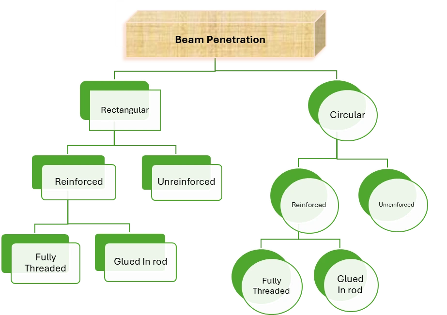
Figure 2: Chart to show Type of penetration hole and its reinforcement type.
Beam Penetration Analysis according to New Eurocode
Reference: – prEN 1995-1-1 section 8.3.6
Holes should preferably be arranged with their center on the neutral axis of the member. An arrangement of holes in areas of the member with dominating shear stresses should be preferred in preference to an arrangement of holes in areas of the member subjected to high bending stresses. The verification of axial and bending stresses of a member which contains holes shall be based on the properties of the net cross-section at the hole position. Circular holes should be preferred to rectangular holes and Eccentric arrangement should only be applied to circular holes.
The effects of stress concentration at holes with a dimension larger than or equal to Minimum of 50mm or 0.1h shall be taken into account in the strength verification of members.
1.Geometrical Limitation
Reference: – prEN 1995-1-1 section 8.3.6
Geometric verification is a critical step in the design and analysis of structural elements, ensuring that the physical dimensions, shape, and layout of a structure or its components meet specific design requirements and constraints. This process helps confirm that the design will perform as intended without compromising the structure’s integrity.
According to prEN 1995-1-1 Section 8.3.6 Table 8.3, geometric verification involves checking various parameters for both reinforced and unreinforced cases. These checks include:
-
- Spacing between penetrations: Ensuring adequate distance between multiple penetrations to maintain the beam’s load-carrying capacity.
- Distance of the penetration from supports and ends of the member: Ensuring that holes are placed far enough from the beam’s support points and ends to prevent weakening the structure.
- Remaining edges after penetration: Verifying that the upper and lower edges of the beam, after making the penetration, maintain sufficient thickness to provide strength.
- Length-to-depth ratio for rectangular holes: Ensuring that the ratio of the length of a rectangular hole to its depth does not exceed specified limits to avoid structural issues.
- Size of the penetration: Checking the dimensions of both circular and rectangular holes to ensure they are within acceptable limits to avoid weakening the beam.
These checks help ensure that the structural element, whether reinforced or unreinforced, remains safe and functional after the necessary penetrations are made.
2. Flexural strength of beams with penetrations
Reference: – prEN 1995-1-1 section 8.3.6.1 (14 & 15)
For circular holes, the bending stresses may be determined by the section modulus of the net cross-section Wnet and for beams with rectangular holes, the effect of additional bending stresses from the frame action should be accounted for.
Text BoxFor circular holes: –
![]()
Text BoxFor rectangular holes: –
![]()
3. Shear strength of beams with penetrations
Reference: – prEN 1995-1-1 section 8.3.6.1 (16)
In beams with holes, the increased shear stresses in the residual cross-section at the hole position should be considered.
![]()
4.Reinforcement Geometry and Design
Reference: – prEN 1995-1-1 section 8.3.6.2
Spacing across the grain (a2 ≥ 5d)
Distance from center of the screw-part in timber to the edge (a3,c ≥ 10d)
Distance from center of the screw-part in timber to end grain (a4,c ≥ 4d)
The reinforcement of a hole in beams should be designed for a design tensile force as follows:

Beam Penetration Analysis according to NZ Wood Design Guides
Reference: – NZ Wood design guide Chapter 12.6
Analysis of the strength and capacity of beam with penetration criteria must pass are Geometrical limitation, tension verification, Flexural Strength Verification, Shear Verification, and Reinforcement condition.
Beams with holes with diameter or depth smaller than or equal to 50mm do not require verification of perpendicular to grain tension stresses, but still need to provide enough flexural and shear strength with net section properties.
1. Geometrical Limitation
Reference: – NZ Wood Design Guides (2020). Chapter 12.6, section 6.1
The concept of “geometrical limitation” in the context of beam penetration in Glued Laminated Timber (GLT) or LVL refers to constraints or factors related to the geometry of a beam that affect its performance and ability to penetrate, or bear loads effectively. Understanding these geometrical limitations is crucial for ensuring that mass timber beams are designed and used in ways that optimize their performance and structural integrity. Conditions to consider in geometric limitation according to NZ Wood Design Guide Chapter 12.6 is based on Reinforced or Unreinforced.
1.1 Geometrical Limitation for Unreinforced Beam
The Maximum penetration diameter or depth dd for unreinforced circular or rectangular holes shall be smaller or equal to 0.15d
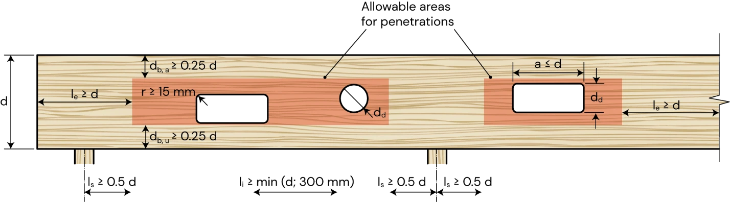
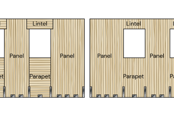
Figure 3: Geometrical limitations for beams with unreinforced penetrations
d = the depth of the beam
dd = the diameter or depth of penetrations for circular and rectangular holes, respectively
le = the distance between the penetration to the end grain of the beam
ls = the distance between the penetration to the support
li = the clear distance between adjacent penetrations
db,a = the depth of the remaining beam portion above the penetration
db,u = the depth of the remaining beam portion under the penetration
a = the length of a rectangular penetration
r = the corner radius of a rectangular penetration
1.2 Geometrical Limitation for Reinforced Beam
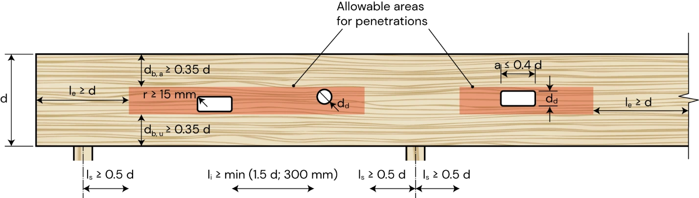
Figure 4: Geometrical limitations for beams with Reinforced penetrations
The maximum penetration diameter or depth dd in timber and glulam beams with circular and rectangular holes, respectively shall be taken as:
dd is less than or equal to 0.3d for penetrations with internal reinforcement (fully threaded screws or glued-in rods) and consider additional limitation of a ≤ 2.5dd for rectangular penetrations.
The maximum penetration diameter or depth dd in LVL beams with circular and rectangular holes respectively, shall be taken as:
dd ≤ 0.4 d in circular holes
dd ≤ 0.35 d in rectangular and the additional limitation of a ≤ 3 dd applies to rectangular penetrations.
2. Flexural shear strength of beams with penetrations
Reference: – NZ Wood Design Guides (2020). Chapter 12.6, section 6.1.2
Flexural shear strength in beams with penetrations refers to the capacity of a beam to resist shear forces while also bearing the effects of flexural (bending) loads, particularly when there are openings or penetrations within the beam’s cross-section. Penetrations can significantly impact the shear strength of a beam. These openings can create stress concentrations and reduce the effective shear area, potentially leading to a reduction in shear strength.
Beams with reinforced and unreinforced penetrations shall be proportioned so that:


Where
M* = design bending action effect at the center of the penetration
M*b,a = design bending action effect from the frame action in the beam portion above the penetration
M*b,u = design bending action effect from the frame action in the beam portion under the penetration
N* = design action effect in tension or compression
Md,n = design capacity in bending of the net section calculated as per NZS AS 1720.1
Md,b,a = design capacity in bending of the beam portion above the penetration calculated as per NZS AS 1720.1
Md,b,u = design capacity in bending of the beam portion under the penetration calculated as per NZS AS 1720.1
Nd = design capacity in tension or compression of the net section calculated as per NZS AS 1720.1
3. Shear strength of beams with penetrations
Reference: – NZ Wood Design Guides (2020). Chapter 12.6, section 6.1.3
The shear strength of beams with penetration refers to the ability of a beam to resist shear forces while incorporating openings in its cross-section. These penetrations can significantly impact the beam’s shear strength and overall structural performance. Understanding how these penetrations affect shear strength is crucial for ensuring safety and stability in structural design.
Text BoxThe design capacity in shear for beams with reinforced or unreinforced penetrations shall satisfy the following:
![]()
![]()
Beams with rectangular penetrations and reinforced with fully threaded screws or glued-in rods shall additionally satisfy:
![]()
4.Reinforcement Geometry and Design
Reference: – NZ Wood Design Guides (2020). Chapter 12.6, section 6.2
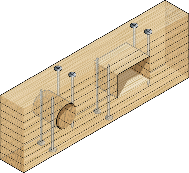
Figure 5: Reinforcement of beams with penetrations with rectangular and round holes reinforced with fully threaded screws or glued-in rods.
Spacing across the grain (a2 ≥ 3d)
Distance from center of the screw-part in timber to the edge (a3,c ≥ 10d) for fully threaded screw and (a3,c ≥ 2.5d) for glued in rod
Distance from center of the screw-part in timber to end grain (a4,c ≥ 4d) for fully threaded screw and (a4,c ≥ 2.5d) for glued in rod
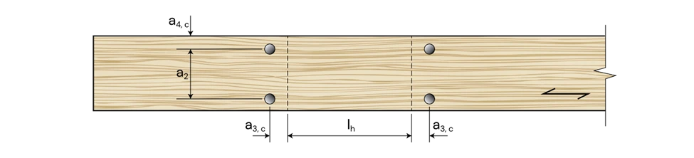
Figure 6: Arrangement of Reinforcement according to grain Direction
The design capacity (Nd,j) for fully threaded screws or glued-in rods as reinforcement shall satisfy the following:
![]()
For fully threaded screw Nd,j is minimum of
![]()
![]()
For glued in rod Nd,j is minimum of
![]()
![]()
Dealing with Beam Penetrations using CLT Toolbox
The CLT Toolbox’s Beam Penetration Calculator is an advanced tool designed to calculate beams with up to five penetrations, whether circular or rectangular. This tool integrates comprehensive checks for geometric limitations, tension, flexural, and shear verifications, streamlining complex calculations into a simple, user-friendly process. Additionally, it automatically verifies reinforcement geometry and design, significantly enhancing your engineering workflow.
The calculator offers design options based on draft Eurocode (prEN 1995:2023), AS 1720:2010/NZ WDG Ch12.6, or a screw supplier’s ETA, allowing users to select the most suitable design standard for their project.
Users can choose between designing beam penetrations with or without reinforcement. When reinforcement is required, the tool provides options to select from a manual input or a range of Screw supply chain partners, including EuroTec GmbH, Rothoblaas, SPAX, SIHGA, and Simpson Strong-Tie, ensuring that the appropriate reinforcement solutions are easily accessible.
This integrated approach simplifies the design process and ensures compliance with relevant standards, making it a powerful tool for engineers working with beams including penetration.