As the construction industry increasingly turns to sustainable materials, Cross-Laminated Timber (CLT) has emerged as a leading choice for structural applications in building construction Hildebrandt J, et al. 2017 . CLT is gaining popularity due to its excellent resistance to both in-plane and out-of-plane loadings, making it one of the key components in lateral load-resisting systems (LLRS).
A LLRS is designed to manage lateral forces that could mainly arise from strong wind and earthquake, using the key components including shear walls, frames, and floor and roof diaphragms. Shear walls play a vital role by transferring lateral loads from the diaphragms to the foundation or supporting systems.
In the strength analysis of CLT shear walls there are a variety of methods which allows for determination of the reaction forces that occur at the supports. “ These methods are also used to determine load carrying capacity of a CLT shear wall “. The methods are mainly based on static equilibrium equations and most of the methods consider the CLT panel as rigid, i.e., the deformation of the CLT panel itself is disregarded in favor of the connections. If not explicitly stated, all the methods resist overturning by hold-downs (HD), and translation by angle brackets (AB).
In the CLT Toolbox Shear Wall Calculator, five cutting-edge analytical methods, derived from state-of-the-art research, are implemented. Below, we summarize the critical aspects of each method, providing a comprehensive overview for engineers and designers. Furthermore, the major issue in the design of CLT shear wall, which is the in-plane shear strength analysis is discussed.
The five models representing load transfer mechanisms
Method I
The first simplified analytical method was developed by Casagrande et al. 2016 which is used to determine the tensile and compressive forces at the connection level, that result from externally applied loads. This method also allows for the evaluation of the load-carrying capacity of a CLT shear wall by considering rigid body rotation and achieving static equilibrium between internal forces and the overturning moment (FR∙h). The point of rotation is assumed to be at the edge of the panel, providing a straightforward approach for analyzing the shear wall’s behavior under load.
![]()
The force in the hold-down (T) due to a lateral load (FR) and vertical load (q) is calculated as:![]()
Where τ is a lever arm coefficient that represent a reduction in width that considers the distance from the panel edge to the hold-down. It is equal to 0.9.
Method II
Method II, introduced by Wallner-Novak et al. 2014, simplifies the nonlinear stress distribution in the timber’s compression zone by approximating it as a rectangular stress block. In this approach, the length of the compression zone (x) is one-quarter of the total wall length. Additionally, a 10% reduction in the effect of the vertical load (q) is applied, accounting for the partial safety factor associated with permanent loads.
![]()
Rotational equilibrium provides the formula for determining the total lateral force (FR):![]()
In the calculation of the overall sliding resistance of the shear wall, Wallner-Novak et al. 2014 accounted for the frictional contribution of the vertical load (q), using a friction coefficient (μ) of 0.4.![]()
Method III
The third method, proposed by Tomasi, 2014, also utilizes a rectangular stress block, similar to Method II, but with a variation in the length of the compression zone. In this method, the position of the neutral axis is represented by x. Tomas, 2014 defines the size of the “stress block” as 0.8∙x, from which the resultant compression force (C) is calculated. This calculation is based on the compression resistance parallel to the grain (fc) and the effective width of the vertical lamellas (tef) of the CLT element.
![]()
![]()
The neutral axis (x) is determined through translational equilibrium by using the tensile capacity (T) of the hold-down, resulting in an expression for x. Tomasi, 2014 assumes that the foundation is significantly stiffer than the CLT element, allowing for this simplified analysis.![]()
The tension force in the hold-down (T) is subsequently determined through rotational equilibrium, centered at the midpoint of the panel:![]()
By applying the expression for the resultant compressive force (C) along with the derived expression for the neutral axis position (x), the total lateral force acting on the wall is then calculated as:![]()
Method IV
Pei et al. 2012 introduced a method that models the CLT panel as a rigid body rotating around one of its corners (See the figure below). Notably, this simplified kinematic method does not directly account for the sliding resistance of the shear wall. Instead, the connection resistance was “back-calibrated” by comparing the hysteretic behavior from numerical modeling with experimental data, ensuring that the load-carrying capacity is constrained by rigid body rotation around one of the panel’s corners. Therefore, caution is advised when comparing this method to other similar approaches.
![]()
To determine the lateral force, the connectors’ elongation and stiffness/strength are considered. Each connector’s tensile strength is proportional to its distance from the panel edge. Using a triangular distribution, the farthest connector (left hold-down in the figure) reaches its full elastic tensile strength (T), while the others, acting as elastic springs, elongate proportionally to their distance (di) from the rotational point.![]()
where dn is the distance from the panel edge to the furthest connector, typically the hold-down.
Using the above simplifications and assuming an evenly spaced arrangement of connectors, the tension force on the hold-down can be computed accordingly.
![]()
where i is counter for the connectors. 1 starting from the connector closer to the edge which is the center of rotation and n is for the furthers connector. s is the spacing between each connector.

Method V
Reynolds et al. 2017 introduced a method similar to Method IV, featuring a triangular distribution of tensile capacity, but with the added consideration of a compression zone. The calculation steps are as follows:
1) Determine the tensile strength (T) of the connector farthest from the rotation point,
2) Calculate the tensile capacity (Ti) of the remaining connectors using a triangular distribution,
3) Calculate the compression zone (x) of the wall, and
4) Determine the lateral resistance (FR) of the shear wall.![]()
where dn is the distance from the panel edge to the furthest connector, and Ti should not exceed the maximum capacity of the actual connector.
For this method also, by doing a back-calculation the tension force on the hold-down can be calculated from an input lateral load, by solving the quadratic equation.

In this method, only the angle brackets outside the tensile zone contribute to resisting the wall’s sliding. However, unlike the typical approach of calculating sliding resistance (FT) solely as the sum of the angle brackets’ resistance, Reynolds et al. 2017 also accounted for the frictional contribution, using a friction coefficient of 0.2, to enhance the sliding resistance of the shear wall.![]()
Summary of the methods that are used to determine the capacity of the CLT shear wall,
| Methods | Summary | |
| Method I, Casagrande et al. 2016 | Analyzes shear walls using rigid body rotation and static equilibrium, with the rotation point at the panel edge, focusing on internal force balance.
|
|
| Method II, Wallner-Novak et al. 2014 | Uses a simplified rectangular stress block and accounts for frictional resistance, providing a more detailed approach to sliding resistance.
|
|
| Method III, Tomasi, 2014 | Similar to Wallner-Novak but with different compression zone length and assumes an extremely stiff foundation with a refined neutral axis calculation.
|
|
| Method IV, Pei et al. 2012 | Treats the CLT panel as a rigid body rotating around a corner with connectors modeled as elastic springs, relying on back-calibrated connection resistance and excluding sliding resistance from the analysis.
|
|
| Method V, Reynolds et al. 2017 | Enhances the triangular tensile distribution method by including a compression zone and factoring in friction to improve sliding resistance evaluation.
|


In-plane shear design of CLT shear wall
Extensive research has solidified design approaches and strength values for CLT under out-of-plane loading. However, in-plane loading of CLT remains less studied, and commonly accepted design methods are still needed, FP innovation,2019. For instance, in Europe, the production and design of CLT products are currently regulated by technical approvals, with ongoing efforts to establish standardized design and verification methods, M Flaig and HJ Bias. However, a general approach for the shear design of CLT members under in-plane loading has yet to be developed.
Strength properties and design methods outlined in different design guides for in-plane shear verification vary significantly. These disparities largely stem from the more complex calculation of shear stresses and deformations in CLT members compared to traditional timber materials. Despite the complexities of the methods and scarcity of data regarding the in-plane shear properties, some research findings have been adopted by various handbooks and design guides, for the verification of in-plane shear behavior of CLT panels.
Before delving into the various in-plane shear verification methods found in different design guides, it’s important to briefly discuss the failure mechanisms of a CLT panel under in-plane loading. Understanding these failure modes is crucial, as they directly relate to the verification methods.
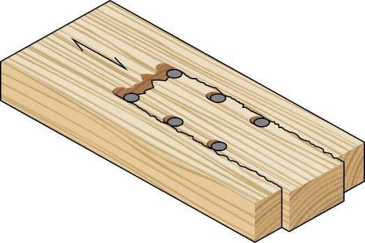
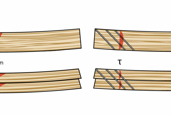
When considering shear stresses in the lamellae and crossing areas, three distinct failure modes can be identified in CLT member subjected to shear stresses, as illustrated in the figure below.

Figure:- Failure modes I, II and III in CLT member subjected to transversal forces in plane direction (from left to right)
Failure mode I is characterized by shear failure parallel to the grain in the gross cross section of the element. The failure occurs in sections between unglued joints with equal shear stresses in longitudinal layers and transversal layers.

Section A-A is relate to location in the beam length direction corresponding to a section through the center of transverse lamination.

Failure mode II is characterized by shear failure perpendicular to the grain in the net cross section of a beam. The failure occurs in sections coinciding with unglued joints with shear stresses only in lamellae perpendicular to the joints.
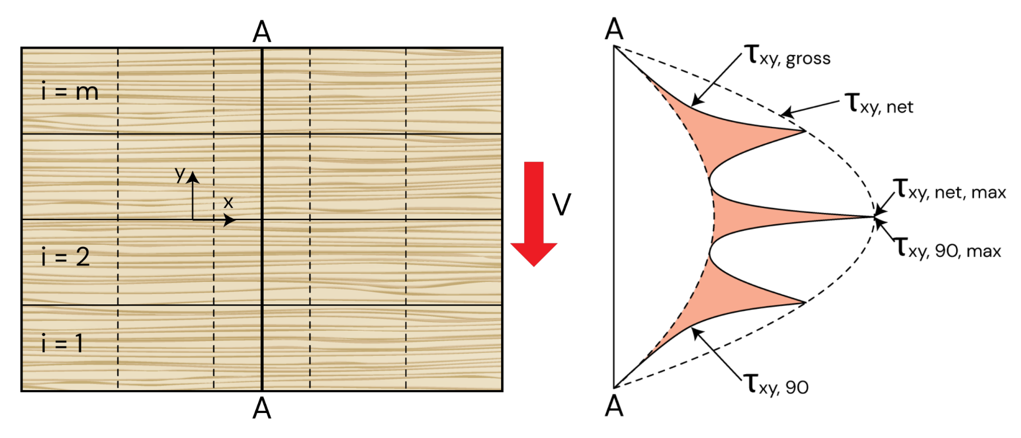
Section A-A relate to location in the beam length direction corresponding to a section through the center of transverse lamination.

Section B-B relate to a location corresponding to the interface between transverse lamination
Failure mode III is characterized by shear failure within the crossing-areas between orthogonally bonded lamellae. The failure is caused by torsional and unidirectional shear stresses resulting from the transfer of shear forces between adjacent layers.

These three failure modes are used in different design guides and handbooks, as a base for checking the in-plane shear strengths of a CLT panels. The two most common design guides or handbook which are incorporated in the CLT Shear wall calculator are ProHolz and FP innovation Canada are summarized in the following table.
| ProHolz, 2014 | FP innovation, 2019 |
| Mechanism 1: Shearing-off failure of the boards along a joint
|
Failure mode I: Shear failure parallel to the grain in the gross cross-section of the beam.
|
| Mechanism 2: Shearing failure of the glued surfaces in the intersection points |
Failure mode II: shear failure perpendicular to the grain in the net cross-section of the beam.
|
| Mechanism 3: Shear failure of the entire plate | Failure mode III: is characterized by shear failure within the crossing areas between the orthogonally glued boards (lamellas).
This failure mode is caused by torsional and unidirectional shear stresses resulting from the transfer of the shear forces between adjacent layers. B) Shear stress perpendicular to the beam axis and C) Torsional sear stress |
References
Casagrande D, Rossi S, Sartori T, Tomasi R. Proposal of an analytical procedure and a simplified numerical model for elastic response of single-storey timber shear-walls. Journal Construction and Building Materials, 2016, Volume 102, 1101–1112.
FP innovation Candian CLT Handbook 2019 edition
Henrik Danielsson, Mario Jelec, and Erik Serrano: Strength and stiffness of cross-laminated timber at in-plane beam loading, 2017
Hildebrandt J., Hagemann N., Thran D. The contribution of wood-based construction materials for leveraging a low carbon building sector in Europe. Sustainable Cities Soc., 34 (2017), pp. 405-418
M Flaig and HJ Bias, Shear strength and shear stiffness of CLT-beams loaded in plane, Karlsruhe Institute of Technology, Germany, ND.
Proholz Wallner-Novak M, Koppelhuber J, Pock K. Information about cross-laminated timber design Fundamentals of statics and construction according to Eurocode. proHolz Austria, 2013, ISBN 978-3-902926-03-6.Austria, November 2014
Pei S, Lindt JVD, Popovski M. Approximate R-factor for Cross-Laminated Timber walls in multi-story buildings. Journal Architectural Engineering, 2012, Volume 19/4, 245– 255.
Reynolds T, Foster R, Bregulla J, Chang W-S, Harris R, Ramage M. Lateral-load resistance of Cross-Laminated Timber shear walls. Journal Structural Engineering, 2017
Tomasi R. CLT course at FPS COST Action FP1004 – Enhance mechanical properties of timber, engineered wood products and timber structures. CLT Training School, University of Trento, 15-17 April 2014.
Great article! I really appreciate the clear and detailed insights you’ve provided on this topic. It’s always refreshing to read content that breaks things down so well, making it easy for readers to grasp even complex ideas. I also found the practical tips you’ve shared to be very helpful. Looking forward to more informative posts like this! Keep up the good work!