Introduction
Reference: Timber Design Handbook and AS 1720.1: 2010 (CL 4.4.4.3)
Connections can be the most critical elements in some structures, representing significant construction costs and design effort. In large spanning structures, the cost of connections and associated fittings may exceed 25% of the cost of all the structural timber members they connect. The detailing of these connections may require over 50% of the design budget, allowing designers an opportunity to be creative in their design of connections. The capacity of a connection is limited by either the strength of the timber into which fasteners are embedded or by the behavior of the fasteners themselves. Most connections (bolted connections) in timber structures are designed for the strength limit state. Most common connections are fabricated from metal components, which means that the failure of the fasteners is often ductile. The serviceability and durability of structures often rely on connection details.
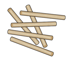
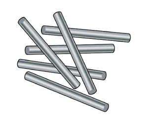
Dowelled connectors are among the large range of connectors available worldwide. Bolts are metal dowels with a head on one end and a nut on the other, which are metal connectors installed into pre-drilled holes in the timber. Larger diameter dowels exhibit similar behavior to bolts. The most obvious difference between dowels and bolts is the absence of both thread and head in the dowel. Despite this distinction, both dowels and bolts serve the same fundamental purpose of load transfer through shear within connections. However, dowels lack the capacity to carry loads in direct tension due to their absence of a head and nut. Consequently, the geometric configuration of the connection profoundly influences its design capacity. In comparison to bolts, dowels present as a less conspicuous connector, seamlessly blending into the structural framework while maintaining robust load-bearing capabilities.
Bolt Distribution
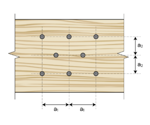
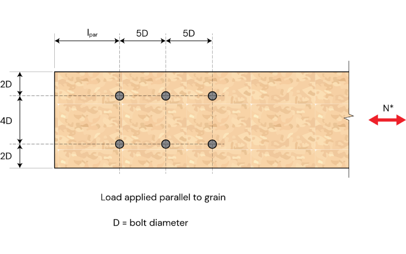
For laterally loaded dowel-type fasteners, there exist various bolt arrangements, including even bolt distribution, circular bolt distribution, and staggered fasteners. Each arrangement offers distinct advantages and considerations in terms of load distribution, structural integrity, and ease of installation. Reference: EN 1995 CL. 8.3.1.2 (Figure 8.7) and prEN 1995 CL. 11.4.3: 2023
Reference: prEN 1995 CL. 11.2.2.2: 2023, EN 1995 CL. 8.3.1.2 and Timber Design Handbook
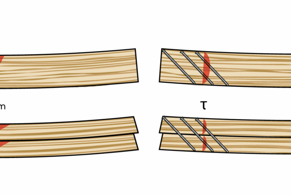
When designing large dowel-bolt connections, it’s crucial to assess their susceptibility to brittle failure modes, especially when subjected to lateral loads parallel to the grain. In scenarios involving multiple fasteners, such as steel-to-timber and timber-to-timber connections, various brittle failure mechanisms like splitting, row shear, block shear, plug shear, and net tensile failure should be considered. However, it’s important to prioritize ductile behavior in timber structures. This ductility can be achieved through mechanisms such as fastener yielding, which helps enhance the overall resilience and safety of the connection.
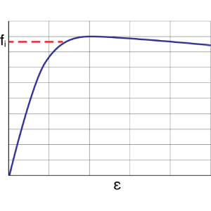
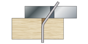
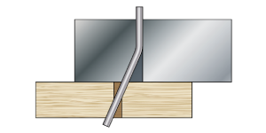
T he design of large dowel-bolts for timber structures hinges on the force direction relative to the grain. Bolts, metal connectors, are inserted into pre-drilled holes in timber, necessitating careful consideration of load paths. Tension members require forces to pass through timber around bolt holes, while compression members can bypass these holes. Inserting a bolt or dowel can redirect forces through the connector’s shank, significantly impacting tension members. In compression members, filled holes provide an alternative load path, compensating for material removed by bolts or dowels. Bolts typically maintain their rigidity under load and do not deform significantly; instead, the surrounding wood deforms around them. The figure below illustrates the typical response of a laterally loaded connection as it approaches its ultimate load. Reference: Timber Design Handbook (Figure 7.18)

Reference: prEN 1995 CL. 11.2.2.2: 2023
The washer diameter should be at least equal to three times the bolt diameter. Verify the washer diameter it is not less than three times the bolt diameter. Washers under the bolt head and nut should have a side length or a diameter of at least 3,4d and a thickness of at least 0,2d.
Connection Configuration
There are different member configurations such as Steel Wood Steel Member configuration (SWS), Wood Steel Wood (WSW), Steel Wood (SW), Plywood Wood (PW), Wood Wood (WW), and Wood Wood Wood (WWW).
-
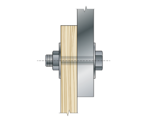
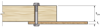
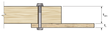
Member Configuration – SWS (Steel Side Plate and Middle timber Member)
-
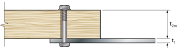
Member Configuration – SW (Single Shear Plane)
-
Member Configuration – PW (Single Shear Plane)
- Member Configuration – WW (Single Shear Plane)
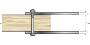
- Member Configuration – WWW (Double Shear Plane)
Analytical Method.
Reference: prEN 1995 CL. 11.2.3.2: 2023 and EN 1995 CL. 8.3.1.2 (Figure 8.7)
The European Yield Model was first developed by Johansen in 1949 and then further popularized by Larsen in the early 1970s. The EYM was developed to predict the resistance of timber connections using dowel-type fasteners, where a combination of fastener yielding and/or timber embedment is observed. It predicts the ductile connection resistance but does not predict how ductile the behavior will be. It’s applicable for bolts, threaded rods, dowels, wood screws, coach screws, timber rivets, and nails. The EYM predicts the resistance of timber connections where the fasteners are working in shear. The EYM does not model brittle failures in timber connections.
The main characteristics of the model are the material embedment strength and thickness, and the fastener yield strength and diameter. In checking the design capacity of a structural element, all combinations of actions shall be considered. Resistance prediction of yielding failure is reliable, embedment and fastener yielding governs. The rope effect is solely noticeable in failure modes involving fastener deformation.
The EYM assumes that materials have an elasto-plastic behavior.
The two main cases covered by the EYM are failure modes for single and double shear joints. For single shear failure modes, there are six possibilities.
i) Embedment failure – No fastener bending
| Descriptions |
Failure Mode |
| a) Fastener does not deform, and the embedment failure is in the top member. | 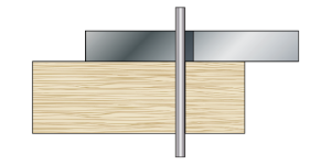 |
| b) Embedment failure is in the bottom member, with no deformation of the fastener. | 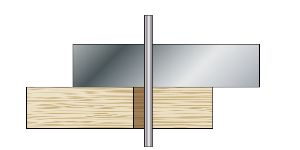 |
| c) The fastener does not deform, but there is embedment failure in both members. | 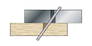 |
ii) Embedment failure- one Plastic hinge in the fastener
|
d) The fastener deforms, with one plastic hinge in the fastener. |
 |
|
e) Mirror image of failure mode d. |
 |
iii) Embedment failure – Two Plastic hinges in the fastener
| f) Two plastic hinges occur, with a combination of embedment (crushing of fibers) and plastic hinges. | 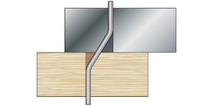 |
For Double Shear failure Modes, there are four:
i) Embedment failure – No fastener bending
| a) Embedment (crushing the fiber) at the side members. | 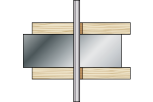 |
| b) All the embedment’s (crushing the fiber) occurring in the middle member. | 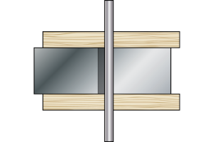 |
ii) Embedment failure- Two Plastic hinges in the fastener
| c) There is a combination of embedment failure on the side and middle members, with a single curvature in the fastener. | 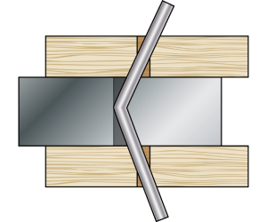 |
iii) Embedment failure – four Plastic hinges in the fastener
-
d) The occurrence of four plastic hinges, two in the center of the joint and the others on the outside. There is a double curvature in the fastener. 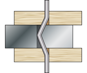
In large dowel bolt design, it’s crucial to consider the absence of any rope effect. Due to this, the fastener must be axially restrained as it undergoes deformation, particularly since there’s no restriction at the end of the dowel. The deformation of dowels generates a load component, often leading to member splitting unless bolts are employed to mitigate this risk.
Dimension Check
Reference: EN 1995 CL. 8.3.1.2 (Figure 8.7) and prEN 1995 CL. 11.4.1 (Figure 11.17): 2023
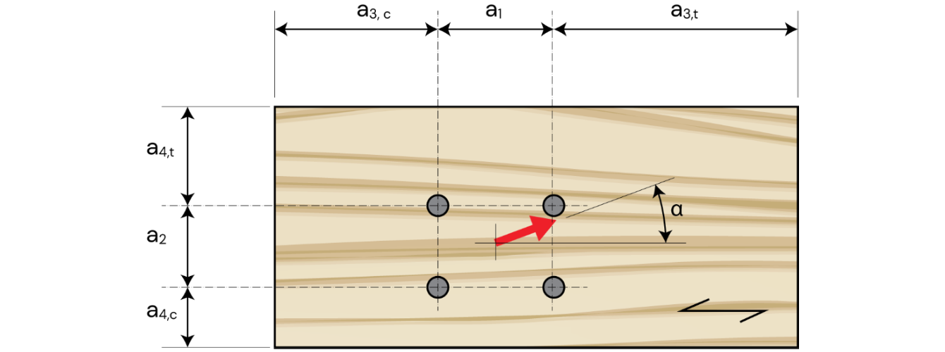
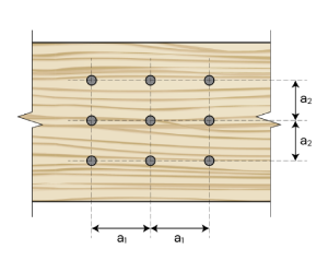
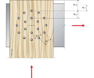
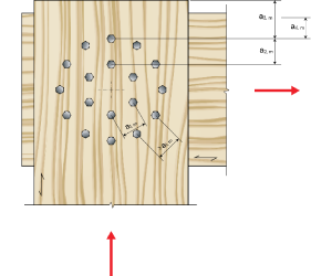
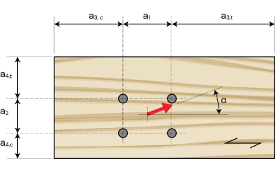
For any dimension and number of bolts provided, it needs to meet the minimum spacing requirement from the code. The spacing provided by the new Eurocode are the max values of the criteria provided by Eurocode 5.1.
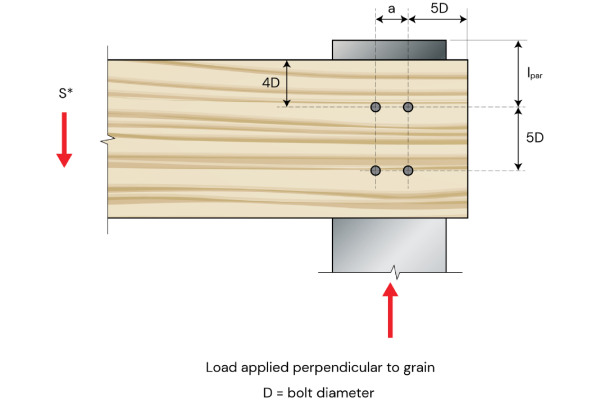
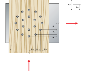
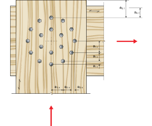
a1 refers to the distance between fasteners (such as bolts or dowels) along the direction of the wood grain. It represents the measurement from one fastener to the next when they are aligned parallel to the natural fibers or grain of the timber. a2 refers to the distance or interval between fasteners or connectors, measured perpendicular to the grain direction in timber or woodbased materials. It represents the spacing between individual fasteners, such as bolts or dowels, placed across the grain in a structural joint.
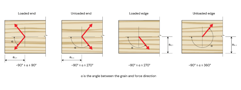
a3t refers to the distance, measured in millimeters (mm), between the loaded end of a structural member, often timber, and the point of connection (bolts or dowels). a4c refers to the distance, measured from the unloaded top or bottom end of a structural member to the point of connection (bolt or dowel) where there is no applied load or external force acting on that end.
Reference: AS 1720.1: 2010 (CL 4.4.4.3) and Timber Design Handbook
Edge distance is the distance between the centerline of a fastener and the edge of the member or timber element. It is measured normal to the edge distance is always measured perpendicular to the side of the piece regardless of the direction of the force.
End distance is the distance between the center of the fastener and the end of the timber. It is always measured parallel to the grain regardless of the direction of the applied force.