Cross-Laminated Timber (CLT) walls are engineered wood panels composed of multiple layers of lumber boards arranged crosswise and bonded together. CLT walls exhibit a high vertical load-bearing capacity compared to conventional timber structures, enabling the construction of tall timber buildings that would otherwise be unfeasible.
CLT Wall Framing:
Framing refers to the structural system that supports CLT panels, ensuring both stability and load-bearing capacity. This system is composed of various components designed to function together, maintaining the structural integrity of the wall. The selection of an appropriate framing system depends on factors such as building height, architectural preferences, local building codes, and structural engineering requirements.
Framing can be classified into the following type:
Platform Type:
Reference: CLT Handbook-Canada:2019
In this system, the floor platform of each story serves as the base for erecting the CLT walls of the next story. As a result, the height of the CLT walls corresponds to the story height. At each level, CLT walls transfer gravity loads from the story above to the CLT floor panels below. Since gravity loads accumulate down the structure, the overall building height is often constrained by the compression perpendicular to the grain resistance of the CLT floor panels on the lowest level. However, this construction method typically incorporates a large number of walls, which can also contribute to seismic load resistance, providing a high degree of redundancy.
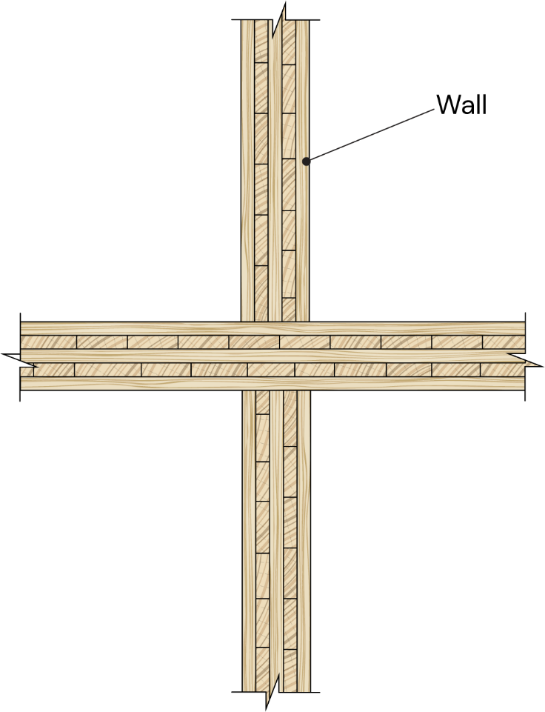
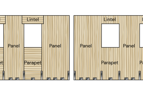
Figure 1: CLT Wall with Platform Framing
Balloon Type:
Reference: CLT Handbook-Canada:2019
In balloon-type CLT structures, the CLT walls extend continuously through the full height of the building, with floor panels attached (or suspended) at each story. In this configuration, the lateral load-resisting system (LLRS) typically consists of a fewer number of walls within the floor plan.
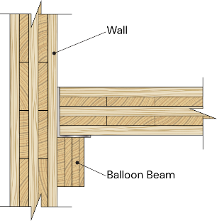
Figure 2: CLT Wall with Balloon Framing
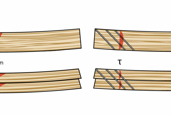
CLT wall eccentricities
Perfectly centered axial loading in walls is rare, as a moment typically arises from the eccentricity of applied axial loads, out-of-plane loading, or both combined. This moment leads to an out-of-plane deflection, ∆. Consequently, the applied axial load acts upon this deflected shape, generating an additional moment due to the P∆ effect. Sources of out-of-plane bending may include eccentrically applied axial loads (due to section loss from fire, unsymmetrical layup, or other factors) and out-of-plane wind forces.
Dealing with CLT Wall Eccentricities using CLT Toolbox
The CLT Toolbox Wall Calculator is a sophisticated tool with a wide range of capabilities. One of its primary functions is determining the eccentricities of a CLT wall using four methods: the CSA 086:19 method, the USA CLT Handbook method, Manual Input, and the Revised Eurocode 23 method. Each approach begins with the first-order eccentricity calculation, followed by the second-order eccentricity calculation, which is performed according to the four methods. The tool ultimately computes the total eccentricity, which is then utilized in the wall analysis.
First-order eccentricity
In wall analysis, it is crucial to consider various sources of First-order eccentricity, including the eccentricity of applied axial loads from above (ep), eccentricity due to axial balloon loads (eb), eccentricity caused by neutral axis shifts, out-of-plane loading, and initial geometric imperfections of the wall.
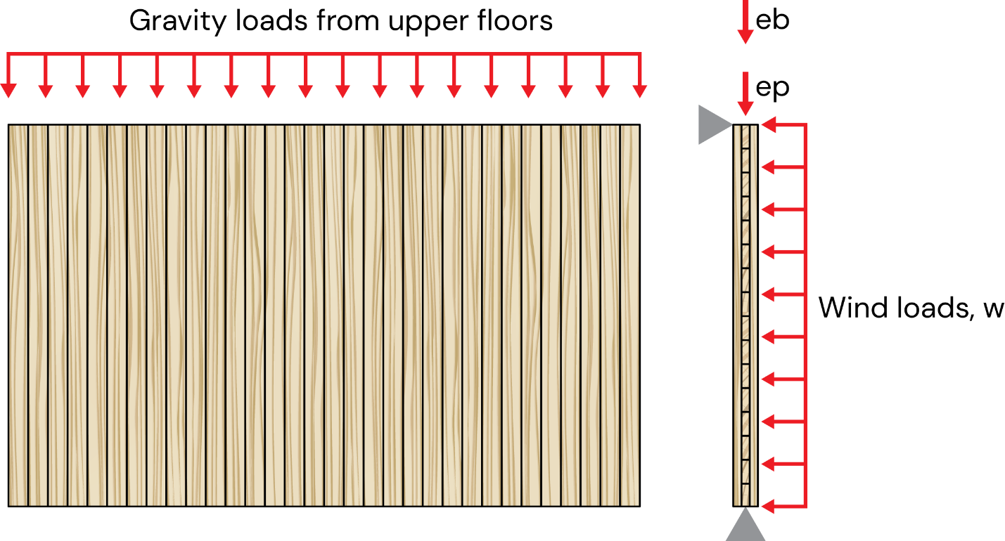
Figure 3: Load Distribution on a CLT Wall
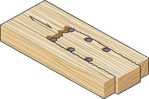
1. Neutral axis shift, eo
In ambient conditions, where CLT elements typically have a symmetrical (balanced) layup, the neutral axis remains at the geometric center. However, if the layup is asymmetric, the neutral axis shifts away from the geometric center. In the case of a fire, charring progressively reduces the cross-section, creating an asymmetrical (unbalanced) layup. As a result, the neutral axis shifts toward the side opposite the fire exposure.
![]()
Where:
tp =Thickness of the wall
yc= Neutral axis location
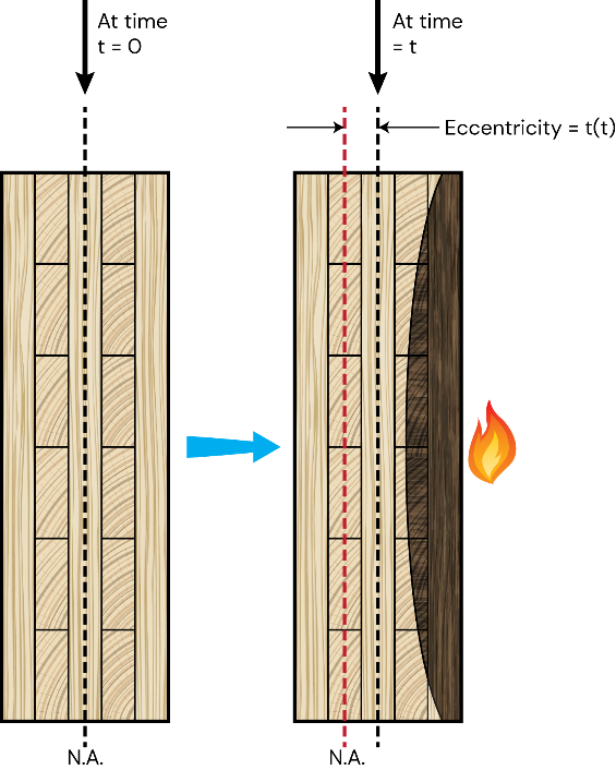
Figure 4: CLT wall element subjected to combined bending and axial compression
The distance from axial load to the neutral axis (governing eccentricity ) can be found as follows:

Where:
eo= Neutral axis shift
ep=actual load eccentricity from axial load above
The distance from axial load from balloon beam to the neutral axis(governing eccentricity ) can be found as follows:

Where:
eo= Neutral axis shift
eb=actual load eccentricity from Axial Balloon Load
2. out of plane wind loading deflection
The deflection (Δ) of a CLT floor panel with length l, subjected to a uniformly distributed load w, can be determined using different analytical methods.
If the analytical method is shear analogy method:
If the analytical method is Gamma or Extended Gamma:
If the analytical method is Timoshenko:
Where EI is the bending stiffness based on the specific method.
3.Initial Geometric Imperfections of the Wall
Initial imperfections are crucial considerations in wall design. In structural analysis, imperfections refer to deviations and inconsistencies arising from factors such as manufacturing tolerances, material variability, and construction inaccuracies. These imperfections cause real structures to deviate from an “ideal” or theoretically perfect condition, potentially influencing their performance under applied loads.
According to CSA 086;19
CLT Handbook-Canada:2019, Section 3.10.4
initial wall imperfections at mid-height of the panel, usually taken as L/500 + h/6, where L is the panel height and h is the panel initial depth, mm.
According to USA CLT Handbook
The CLT Toolbox CLT Wall Calculator allows users to input initial wall imperfections manually, as the Handbook does not provide a formula for the calculation.
According to Revised Eurocode 23
Reference: prEN 1995-1-1:2023, Section 7.3.1
The equivalent bow imperfection (e) should, at a minimum, be considered as follows:

Where l is the height of the Wall.
Second order Eccentricity
Second-order effects, also referred to as P-delta effects, occur when an eccentric axial force (such as self-weight or an applied load), in combination with axial and horizontal loads, generates a bending moment and additional displacement. In a CLT wall assembly, these effects (P-Δ effects) can also develop due to charring of the fire-exposed surface, which reduces the cross-section and impacts the structural stability of the wall.
According to CSA 086;19
CLT Handbook-Canada:2019, Section 3.10.4
The following formula calculates second-order eccentricity:
A) for balloon framing


Where:
Δf = Deflection due to out-of-plane loading (bending), in mm
e1 =Governing Eccentricity of the axial load, in mm
e2 =Governing Eccentricity of the axial load from balloon beam, in mm
Δ₀ = Initial wall imperfections at mid-height of the panel, typically taken as L/500 + h/6, where:
L = Panel height, in mm
h = Initial panel depth, in mm
B) for Platform framing

According to USA CLT Handbook
CLT Handbook-USA:2013, Chapter-8,Section 4.1.9
The following formula calculates second-order eccentricity:
A) for balloon framing

Where:
e1 =Governing Eccentricity of the axial load, in mm
e2 =Governing Eccentricity of the axial load from balloon beam, in mm
Δ₀ = Initial wall imperfections from user input
Total eccentricity:
![]()
![]()
Where:
e1 =Governing Eccentricity of the axial load, in mm
e2 =Governing Eccentricity of the axial load from balloon beam, in mm
Δ₀ = Initial wall imperfections from user input
Δw= Deflection due to out-of-plane loading (bending), in mm
B) for Platform framing

Total eccentricity:
According to Revised Eurocode 23
Reference: prEN 1995-1-1:2023, Section 7.4.2
For a member subjected to an equivalent bow imperfection ez or ey with a constant design compressive force 𝑁Ed and an applied uniaxial design bending moment about either the y- or z-axis, the design non-linear moment ![]() about the respective axis may be determined as follows:
about the respective axis may be determined as follows:

With:


Where:
αc, y/z is the amplification factor for critical normal forces;
δy/z is the Dischinger-coefficient taking into account the respective distribution of either My, Ed or Mz,Ed;
Ny/z, is the critical force for flexural buckling about the respective axis.
E0, d is the design modulus of elasticity parallel to grain ;
I y/z is the second moment of inertia about the y- or z-axis, respectively;
ly/z, ef is the effective compressed length.
Furthermore, in the CLTTOOLBOX Wall calculator, moment calculations are performed separately for each method, considering the respective eccentricity.
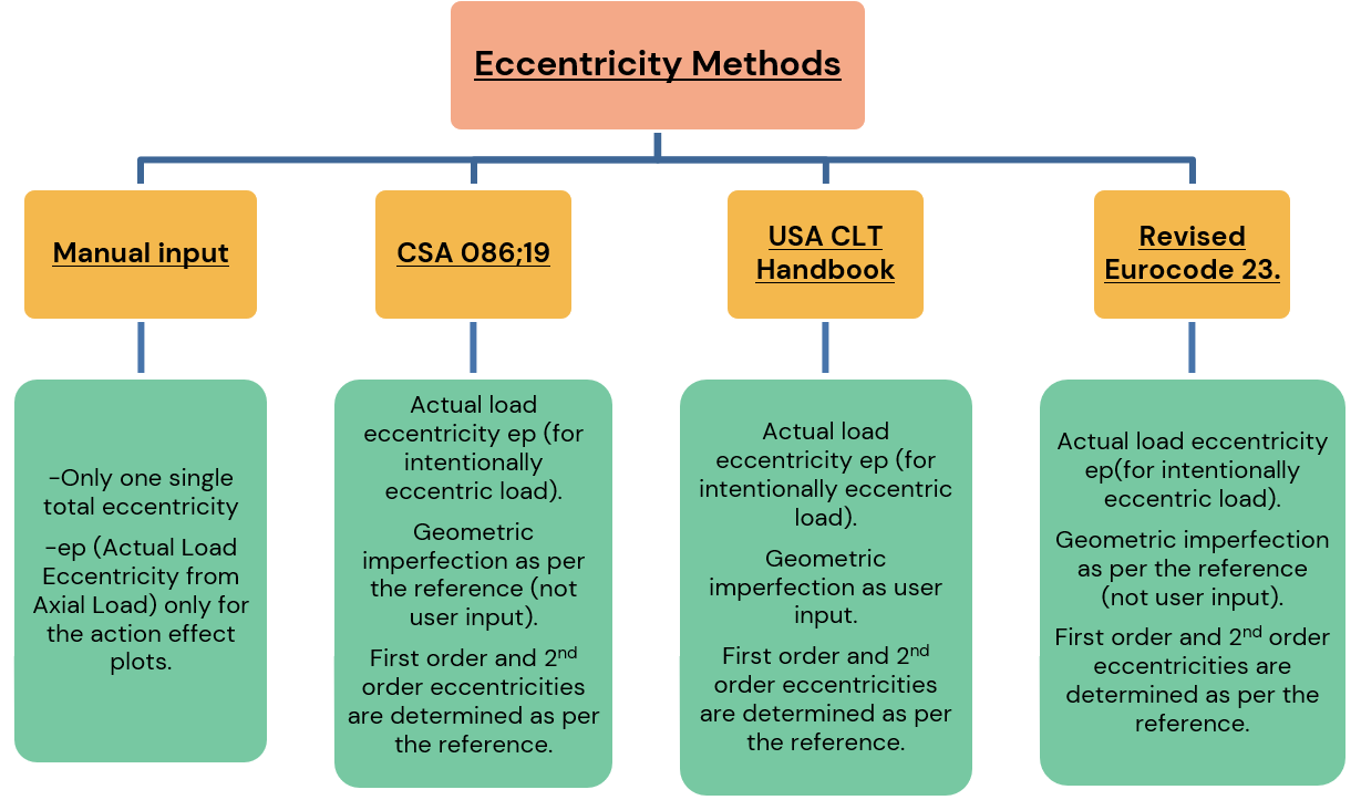
Figure 5: Eccentricity Considerations for Platform-Type CLT Wall
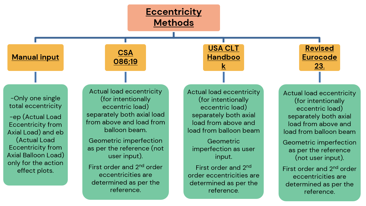
Figure 6: Eccentricity Considerations for Balloon-Type CLT Wall